Piezoelectric Diaphragm Underwater Acoustic Voltage Calculator
Overview
This tool estimates the open-circuit voltage response of a MEMS acoustic sensor consisting of a circular clamped silicon diaphragm with a thin piezoelectric film deposited on its top surface. The device is intended for underwater (submerged) operation.
Given the geometry, material properties, and the acoustic pressure amplitude at a chosen frequency, the calculator outputs the open-circuit voltage across the piezoelectric film, the resonant frequency in both air and water, and the peak center deflection. Frequency response plots (voltage and deflection, both in dB on a log-frequency axis) and the in-plane strain distribution across the diaphragm radius are also provided.
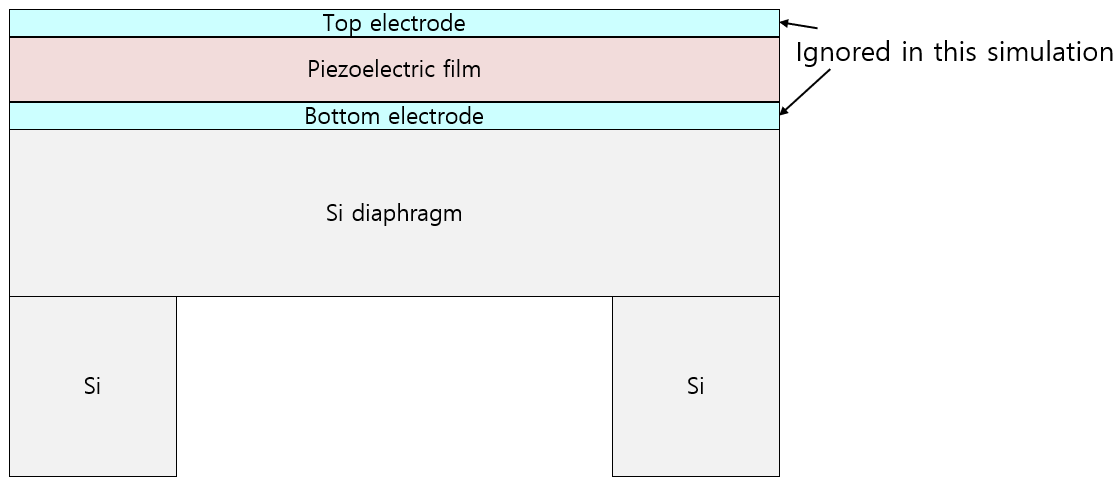 Fig. 1 Structure of MEMS hydrophone. Both electrodes are ignored in this simulation.
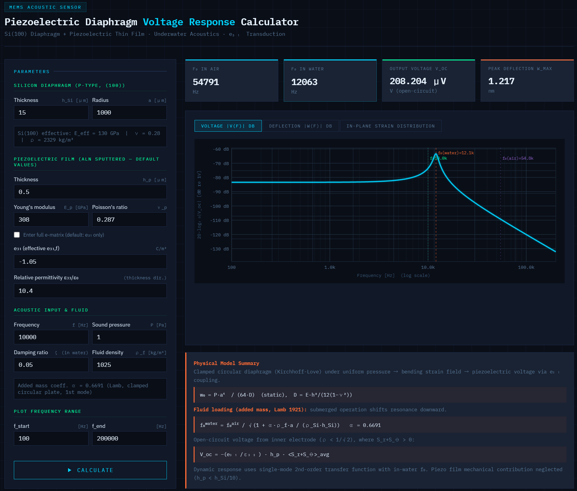 Fig. 2 Calculator interface: parameter panel (left), frequency response and strain
distribution plots (right).
Fig. 2 Calculator interface: parameter panel (left), frequency response and strain
distribution plots (right).
Physical Model
Mechanical analysis
The diaphragm is modeled as a clamped circular plate under uniform pressure loading, following Kirchhoff–Love thin-plate theory. The silicon substrate is P-type (100)-oriented, for which an isotropic effective modulus E = 130 GPa and Poisson’s ratio ν = 0.28 are used as representative average values for in-plane bending. The piezoelectric film thickness is assumed to be less than one-tenth of the silicon thickness, so its mechanical contribution to plate stiffness is neglected.
The static center deflection and bending strain field are given analytically:
where ρ = r/a is the normalized radius, a is the plate radius, h is the silicon thickness, and D is the flexural rigidity.
Dynamic response at frequency f is obtained from a single-mode second-order transfer function with resonant frequency f0 and damping ratio ζ.
Fluid loading (added mass)
When the diaphragm operates submerged, the surrounding fluid increases the effective vibrating mass, shifting the resonant frequency downward. The correction follows the Lamb (1921) added-mass model for a clamped circular plate:
The added-mass coefficient α = 0.6691 applies to the fundamental mode of a clamped circular plate. The fluid density ρf is a user input (default: 1025 kg/m³ for seawater).
In-plane resonant frequency (in air)
The fundamental resonant frequency in air is:
where α01² = 10.2158 is the squared eigenvalue for the first axisymmetric mode of a clamped circular plate (Leissa).
Piezoelectric voltage (e31 transduction)
Under open-circuit conditions (no charge flow), the electric displacement D3 across the film thickness is zero. For a film with in-plane isotropy (e.g. c-axis AlN), this gives:
where hp is the film thickness, ε33 is the out-of-plane permittivity, and ⟨ ⟩ denotes the area average of the in-plane strain sum over the inner electrode region (ρ < 1/√2 ≈ 0.707), where Sr + Sθ > 0.
Calculator Interface
Input panel (left side)
Parameters are grouped into three sections. All geometric inputs are in micrometers (μm).
| Section | Key parameters |
|---|---|
| Geometry | Silicon diaphragm thickness hSi, diaphragm radius a, piezoelectric film thickness hp. Default values correspond to a typical MEMS IR pixel structure. |
| Piezoelectric film | Young’s modulus, Poisson’s ratio, and either a single e31 (effective) value or the full 3×6 e-matrix. Default values are for sputtered AlN from literature. The out-of-plane relative permittivity ε33/ε0 is also entered here. |
| Acoustic input & fluid | Operating frequency, sound pressure amplitude, damping ratio ζ (default 0.05 for submerged operation), and fluid density. |
| Plot range | Start and end frequency for the response plots (default 100 Hz – 200 kHz). Both axes use logarithmic scaling. |
Result cards (top right)
After clicking Calculate, four summary values are shown: resonant frequency in air, resonant frequency in water, open-circuit voltage at the entered frequency, and peak center deflection.
Plots
Three plot tabs are available:
- Voltage |V(f)| dB — Open-circuit voltage vs. frequency in dB (re 1 V), log-log axes. Vertical markers indicate f0 in water (orange) and in air (purple). A green marker shows the currently entered frequency.
- Deflection |w(f)| dB — Center deflection vs. frequency in dB (re 1 nm), same axis convention.
- In-plane strain distribution — Radial (Sr), tangential (Sθ), and their sum as a function of normalized radius ρ = r/a at the current frequency. The node point at ρ ≈ 0.707 where the sum changes sign is indicated.
Assumptions and Limitations
- Linear, small-deflection plate theory (Kirchhoff–Love). Not valid if center deflection exceeds roughly h/5.
- Single-mode resonance model; higher modes are not included.
- Electrode stress and residual film stress are neglected.
- The piezoelectric film is assumed mechanically transparent (hp < hSi/10).
- No acoustic radiation damping; the damping ratio ζ must be set by the user based on measurements or estimates.
- Fluid loading is one-sided (single fluid half-space model).
Default Values Reference
| Parameter | Default | Note |
|---|---|---|
| Pixel length l | 35 μm | Square diaphragm side |
| Diaphragm radius a | 1000 μm | Set independently for acoustic modeling |
| Si thickness hSi | 15 μm | |
| Film thickness hp | 0.5 μm | AlN sputtered |
| Ep (AlN) | 308 GPa | Sputtered AlN, literature |
| νp (AlN) | 0.287 | |
| e31 (AlN) | −1.05 C/m² | Effective value |
| ε33/ε0 | 10.4 | AlN, thickness direction |
| Fluid density | 1025 kg/m³ | Seawater |
| Damping ratio ζ | 0.05 | Submerged estimate |
| Sound pressure | 1 Pa | ≈ 94 dB re 20 μPa in air |